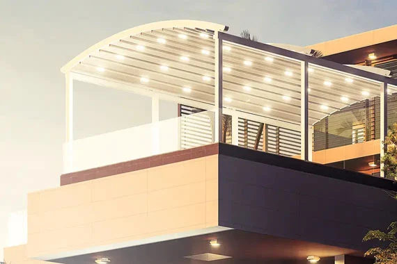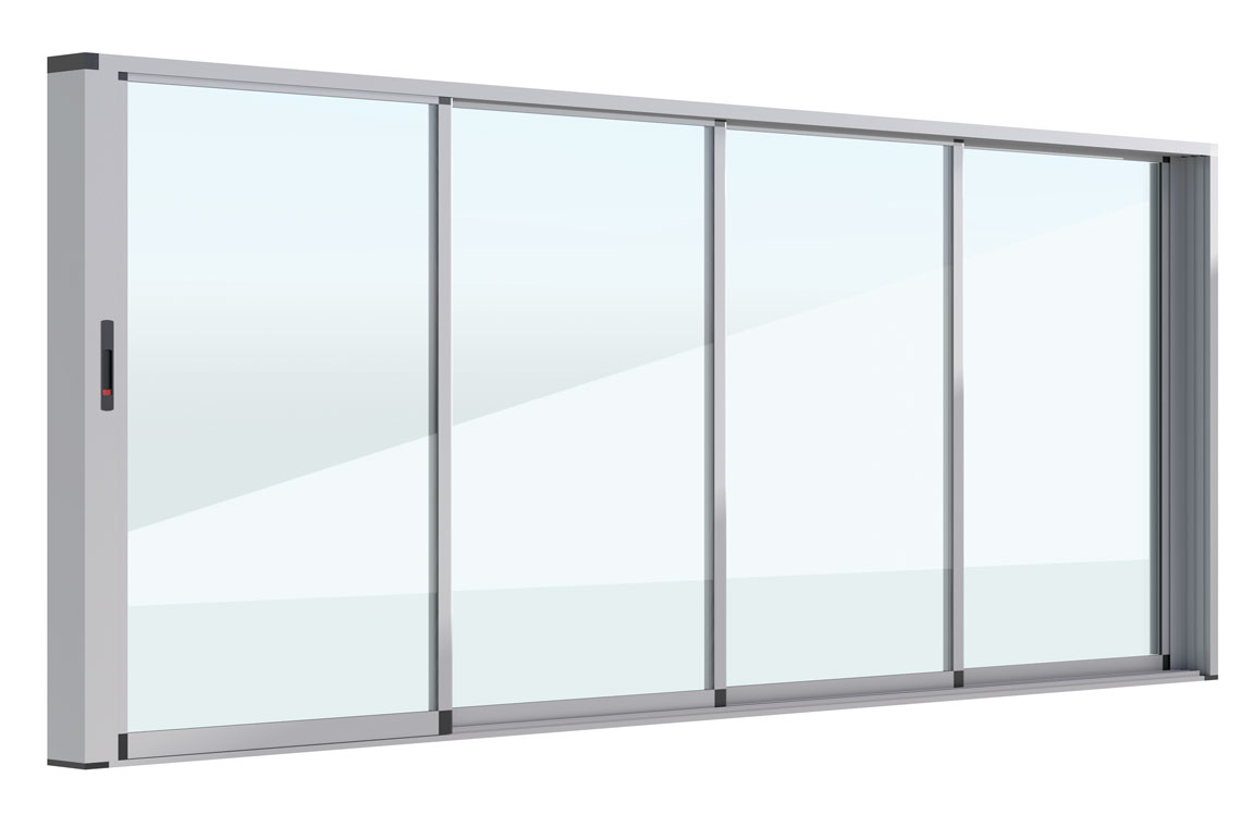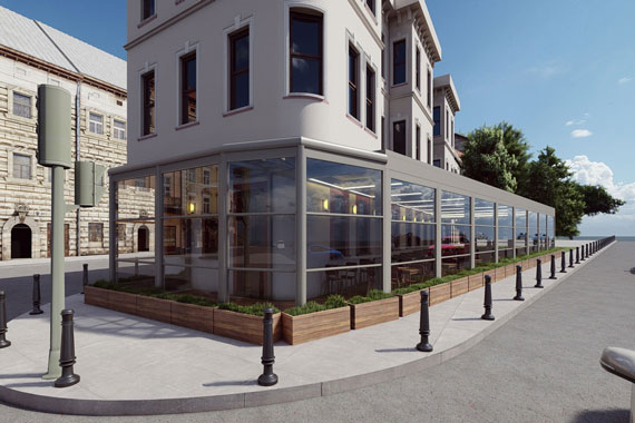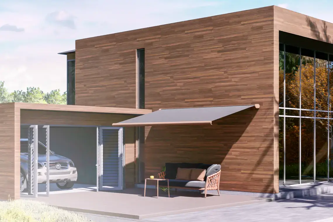
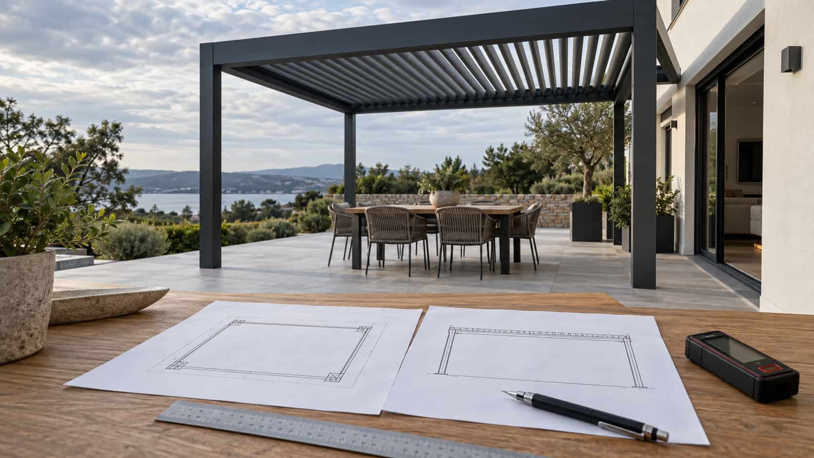

Integrating a bioclimatic pergola system correctly into an architectural project requires aesthetic appearance, structural safety and functional performance to be evaluated together. Before technical drawings are prepared, the dimensions of the installation area, the building’s load-bearing characteristics, façade connections, floor elevations and environmental loads must be examined in detail. This ensures that the pergola becomes an applicable, production-ready system that remains compatible with the existing architectural design.
The planning process involves more than defining the pergola’s width and height. The operating direction of the movable louvers, motor position, electrical connections, rainwater drainage, anchorage points and installation tolerances must also be shown in the project. A properly prepared architectural pergola project enables architects, engineers, manufacturers and installation teams to work with the same technical data throughout the process.
What Is a Bioclimatic Pergola Technical Drawing and Why Is It Required in an Architectural Project?
A technical drawing is a scaled project document that explains the pergola system’s position, dimensions, structural components and operating principles within the architectural space. Column positions, beam spans, louver directions, connection points and relationships with surrounding structures are defined through plans, elevations, sections and detail drawings. These documents provide the main application reference for production and installation teams.
A properly prepared bioclimatic pergola technical drawing helps identify conflicts that may not be visible during the initial design stage before production begins. Façade cladding, door openings, parapets, utility lines and varying elevations can be checked on the drawings. This reduces the need for improvised solutions on site while limiting risks such as material waste, installation delays and dimensional incompatibilities.
How Does the Bioclimatic Pergola Technical Drawing Process Proceed?
The technical drawing process begins with collecting existing architectural documents and information about the installation area. The site plan, floor plans, façade elevations, building sections and available structural projects are evaluated together. The intended use of the pergola, the area it will cover, its opening direction, whether it will be freestanding or attached to the building and the circulation areas around it are then determined.
Once the collected information has been transferred to a preliminary layout, the main dimensions and module structure of the system are established. Structural profiles, column positions, motor and louver placement, drainage routes and connection details are added to the project. The design is reviewed in terms of architectural expectations, structural requirements and production limitations before proceeding to the preparation of application details.
How Are Architectural Project and Installation Area Data Reviewed?
When architectural documents are reviewed, the clear span of the installation area, façade geometry, slab boundaries, parapet height and nearby fixed elements are identified. Door and window openings, sunshades, utility outlets, rainwater pipes and exterior cladding systems are also checked. Dimensions shown in the drawings are compared with site measurements. Any conflicting or outdated information that does not reflect the current site conditions must be clarified before it is transferred to the application project.
How Is a Bioclimatic Pergola Layout Plan Prepared?
The layout plan shows the exact position of the pergola in relation to building boundaries, façade axes and functional areas. Columns should not obstruct circulation, restrict door openings or negatively affect furniture placement. The louver direction is determined by considering solar control, prevailing winds, rainwater drainage and the relationship with the surrounding view. Module connections and external system dimensions are planned to preserve architectural integrity while supporting practical and accurate installation.
How Is a Site Survey Conducted for a Bioclimatic Pergola?
A site survey involves more than measuring the width between two points. Structural axes, diagonals, heights, elevation differences, wall verticality and floor slopes must be measured together. Values obtained using laser meters, levels and suitable mechanical measuring equipment should be compared with the architectural project, while any differences must be recorded separately in the survey documentation.
Accurate bioclimatic pergola dimensioning requires measurements to be taken from fixed and verifiable reference points. If the cladding, screed or façade installation has not yet been completed, the thickness of the finished surfaces must be included in the calculations. Measurements taken at multiple points help identify non-parallel walls, uneven floors and other site conditions that could affect production or installation.
How Are Clear Span, Axis, Elevation and Slope Measurements Determined?
When measuring the clear span, fixed boundaries such as columns, walls, parapets and façade cladding are used as reference points. Structural axes and finished surface boundaries must be distinguished to prevent incorrect production dimensions. Upper and lower elevations are measured at several points to identify floor or ceiling slopes. The slope toward the intended drainage direction is also recorded. Diagonal measurements confirm whether the area is square, and any geometric deviation is transferred to the technical drawings.
How Are Installation Clearances and Application Tolerances Calculated?
Installation clearances are determined according to profile sections, connection components, the operating space required by moving parts and the surface characteristics of the existing structure. Sufficient space should be left between the façade cladding and pergola for maintenance and waterproofing applications. Production tolerances depend on the scale of the system and the selected connection method, while uncertainties in site measurements must also be considered. Excessive clearances should be avoided because they can cause visual gaps and difficulties in enclosure details.
Which Details Should Be Included in a Bioclimatic Pergola Technical Drawing?
The technical drawing set should include façade elevations, system sections, profile connections and installation details in addition to the general layout plan. The total width, projection, finished height, column axes and module spacing of the pergola must be dimensioned clearly. The relationship between moving parts and fixed building elements should also be shown using understandable symbols, notes and technical references.
A comprehensive pergola detail drawing should minimise points that may otherwise be open to interpretation during production and installation. Profile sections, connection components, motor position, cable routes, anchorage types and drainage outlets must be included in the drawing set. Material codes, surface finishes and critical installation notes further strengthen technical coordination between the architectural, production and site teams.
How Are Structural Profile and Connection Details Shown?
Structural system details show the column and beam sections, profile wall thicknesses, connection methods and positions of fastening elements. At points where the pergola is attached to the existing structure, components such as brackets, plates, mechanical anchors or chemical anchors are explained through detailed sections. The method used to connect the system to concrete, steel, masonry or different façade layers should be specified separately. The installation sequence and access requirements for concealed connections should also be supported with application notes.
How Are Movable Louvers, Motors and Mechanical Components Planned?
Louver placement is determined according to the system span, rotation axis, opening angle and operating clearances between individual louvers. The motor, drive mechanism and transmission components should be positioned so that maintenance can be performed when necessary. The route of electrical cables through the structural profiles, together with the locations of junction boxes and control units, must be shown on the drawings. Open and closed position checks help prevent movable components from conflicting with façades, walls or supplementary enclosure systems.
How Are Rainwater Drainage Details Added to Technical Drawings?
Sections should show how rainwater collected by the louvers is transferred to gutters, internal column channels and final drainage outlets. Gutter dimensions, water collection direction, internal downpipe routes and outlet elevations must be compatible with one another. Discharge points should prevent water from flowing back toward the façade or occupied areas. If the system connects to a floor drain, the pipe diameter, connection elevation and maintenance access must be coordinated with the relevant mechanical installation project.
How Are Structural Calculations and Load Checks Performed for a Bioclimatic Pergola?
Structural assessment ensures that the pergola operates safely under its self-weight as well as wind, snow and other loads associated with the intended use. System span, column spacing, profile sections and connection points are evaluated according to the environmental conditions of the project location. For building-attached pergolas, qualified engineers must also verify whether the existing structural system can safely carry the additional loads.
Calculation results may affect not only profile selection but also anchorage arrangements and module dimensions. Deflection limits in wide spans, force transfer at connection points and the behaviour of louvers under wind loads must be evaluated together. Selecting standard profiles without considering the project’s region, building height, terrain characteristics and surrounding structures can create significant structural and operational risks.
How Do Wind, Snow and Dead Loads Affect a Pergola Project?
Wind loads vary according to the height of the structure, its exposure, façade position and regional wind conditions. Snow loads are assessed based on the geographical region, altitude and roof geometry. Dead loads include profiles, louvers, motors, gutters and additional elements such as lighting fixtures or glass enclosure systems. These values influence profile dimensions, column spacing and connection design, helping prevent excessive deflection, structural instability and overstressing at critical fastening points.
How Are Anchorage and Structural System Decisions Made?
Anchor selection depends on the material, thickness, strength and edge distances of the surface to which the pergola will be connected. Mechanical or chemical anchors may be considered for reinforced concrete surfaces, while bolted or welded connections may be planned for steel structures. Façade cladding should not be treated as the primary structural surface; loads must be transferred safely to the building’s main structure. Anchor plate dimensions, fastener quantities and installation depths should be specified according to structural calculation results.
How Is a Pergola Project Coordinated with Architectural, Electrical and Mechanical Disciplines?
Interdisciplinary coordination enables the pergola to function not only through its own components but also in harmony with surrounding building and utility systems. The architectural team checks circulation areas, façade integrity and finishing details. The electrical team plans connections for motors, lighting, sensors and automation systems, while the mechanical team coordinates rainwater drainage and any related infrastructure requirements.
Without proper coordination, the motor cable may conflict with a structural connection, the drainage outlet may remain too far from the floor drain or a pergola column may obstruct a doorway. Current drawings from different disciplines should therefore be compared using the same reference system. Every revision must be transferred to the relevant drawing sets and shared with the teams to prevent production or infrastructure work from proceeding according to outdated information.
How Are Façade and Structural Connections Coordinated?
Façade connections require the cladding layers, thermal insulation, waterproofing and main structural surface to be examined together. The pergola should not be fixed only to decorative cladding; the load path must continue safely to the reinforced concrete or steel structure. Suitable connection details should prevent thermal bridging, water infiltration and cladding deformation. The visual relationship with façade modules, joints and window axes should also be considered alongside structural requirements.
How Are Electrical, Automation and Water Drainage Lines Planned?
The power supply route, cable size, junction boxes and control unit positions for the motor and automation systems must be determined in advance. If rain, wind or sunlight sensors are used, their locations should allow them to detect environmental conditions accurately. Lighting and motor cables must be routed through accessible channels that support future maintenance. Drainage lines should be separated from electrical components and directed with sufficient slope toward a floor drain or suitable external discharge point.
How Does the Bioclimatic Pergola Shop Drawing and Production Approval Process Proceed?
A shop drawing converts the approved architectural layout into manufacturable components and detailed installation information. The dimensions, cutting angles, drilling positions, connection methods and part codes of each profile are defined at this stage. The relationships between modules, columns, beams, louvers, gutters and mechanical parts are checked according to the required production and installation tolerances.
The completed pergola shop drawing set should be reviewed by the architectural team, structural engineer, manufacturer and application representatives. All requested revisions must be consolidated into one current drawing set, with the approval status indicated clearly. Production should not begin before site measurements are verified and critical details receive written approval. This reduces the risk of using outdated revisions or manufacturing components that are incompatible with site conditions.
What Are the Most Common Technical Drawing and Dimensioning Errors?
One of the most common mistakes is using nominal dimensions from the architectural project as production dimensions without verifying them on site. Failing to account for finished surface thicknesses, taking measurements from only one point and omitting diagonal checks can create significant geometric incompatibilities. Positioning columns within door openings, circulation routes or utility areas is another frequent issue that usually originates during the layout stage.
Other errors include omitting drainage slopes, overlooking motor access, connecting the pergola only to façade cladding and planning electrical infrastructure after production. Distributing drawings without revision numbers can also cause different teams to proceed with conflicting information. A documented site survey, interdisciplinary review, revision tracking and formal production approval process should therefore be completed before manufacturing begins.
What Should Be Checked Before Approving a Bioclimatic Pergola Application Project?
Before approval, the system’s external dimensions, clear spans, column axes, finished heights and floor elevations must be compared with verified site data. The louver direction, motor position, operating clearances, profile sections, connection methods and drainage routes should be consistent across all drawings. Plans, elevations and sections must also be reviewed together to identify any dimensional or positional discrepancies.
For the pergola application project, structural calculations must be completed and the suitability of anchorage details and electrical-mechanical infrastructure must be confirmed. Colours, surface finishes, accessories and automation options should be finalised in writing. Revision numbers and approval dates must be added to the drawings, after which the production set should be distributed to all stakeholders as a single current version.
How Does Tenteks Manage the Technical Drawing Process for Bioclimatic Pergola Projects?
Tenteks manages the technical drawing process for bioclimatic pergola systems using site measurements and the architectural data of each project. The system layout considers intended use, façade relationships, structural connection points, louver direction and water drainage requirements together. Plans, elevations, sections and necessary connection details are prepared according to the project so that production decisions can be made through controlled technical documentation.
Before the drawings are transferred to production, system dimensions, module distribution, motor placement and installation conditions are reviewed. Architectural or site-related revisions are added to the current project set so that production and installation teams work with the same information. This approach supports component compatibility in custom-sized projects and helps identify possible dimensional, connection and infrastructure issues before installation.
How Can You Receive Bioclimatic Pergola Site Survey, Project Planning and Quotation Support from Tenteks?
For an initial project assessment, the location, approximate dimensions and recent photographs of the installation area can be shared together with available architectural drawings. The intended use, required coverage area, automation options, colour preferences and supplementary enclosure systems should also be specified. This information supports preliminary evaluation and helps identify the technical points that must be checked during the site survey.
Through Tenteks’ site survey, project planning and quotation support, site conditions, system dimensions, structural requirements and application details can be evaluated together. Once the technical scope has been confirmed, product configuration, production requirements and installation conditions can be planned specifically for the project. The quotation can therefore reflect the system’s technical components and site requirements rather than being calculated solely according to area.